The vast majority of our restoration has dealt with the ram and pump. We have recorded much of our work and will gather our success and failures here. We begin with the a summary of what we have learned, followed by postings starting with the purchase of our lift and the rest of the story.
Original post from 02/2004
Newgren Lift
While the Monroe system is the more well know lift, the Newgren Equipment Company lift was also available through Willys dealers. We were searching for a more common Monroe hitch, when we found a Newgren lift on e-bay. What we really purchased was “part” of a lift. We picked up a frame, ram (hydraulic cylinder), reservoir and control valve. We were missing the hydraulic pump and the implement lift arms.
Hunk o’ rust
We know little history of our lift. We picked it up in northern Ohio and were told that it had been taken off a 2a parts jeep. From the rusted body piece still bolted to the front control rod (visible in the picture), we do know it was a red jeep. A PTO gear box was still attached to the frame. It was missing the rear shaft flange. It was not part of the original lift and would have been part of the original jeep’s PTO package. We do believe it is an early model The reservoir and control rods vary only slightly from the 1947 instruction manual we obtained from fellow Newgren owner Daron W.
The first task was to take the components off the frame. This was straight forward, since the ram is held by a single pin and the reservoir is held on by a single strap attached with two screws. Once the ram was removed, it was clear that a complete rebuild was in order. We took the ram to a local hydraulics shop. Once we explained what we were restoring, they suggested that they restore the ram, instead of trying to substitute a new one. $350 later, we have a beautiful, like new ram.
The frame had a broken lift arm and we took it to a local welding shop for repairs. They cut the short arm from the shaft and reattached it with a stronger weld. The frame is a fairly simple form and was in good shape, except for surface rust.
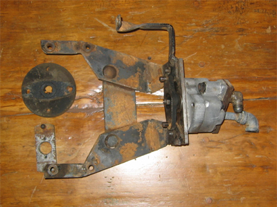
The reservoir needed only a good wire brushing and cleaning. This was followed by a quick coat of paint for the frame and reservoir. In the bottom view, you can see the key components. The reservoir, attached to the frame by a short strap and two screws. The rear control rod is clearly visible, the hooked end is attached to the control valve. The ram is in the extended position. The reservoir drain plug is visible, and the pump return line fitting is shown at the top right corner of the picture.
Like a glove
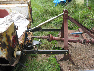
Mounting of the frame is straight forward once you have rerouted the exhaust, and removed the drawbar. The frame mounts under the bed, using the same mounting holes as the drawbar. Pictured is the assembled frame, ready to roll under the jeep. We had the frame on an old mechanic’s creeper and used bottle jacks to position the lift into place. Pictured is a top view of the lift. One hose goes from the control valve to the ram. The second hose goes from the bleed-down fitting on the ram to the reservoir. The pump pressure side hose attaches to the fitting on top of the valve. The connections on the top of the reservoir are difficult to reach, once the lift is installed. The shiny pipe extending from the rear of the reservoir is the filler tube.
The lift frame was engineered to fit like a glove and it does. The rear lift frame member attaches with two bolts and uses the holes in the frame cross member formerly occupied by the drawbar braces. As can be seen in the picture, the rear of the lift bolts directly to the rear frame cross member. The lift frame is a simple bolt on application.
The rear control lever (the other lever is located next to driver’s seat) is visible, just to the right of the hitch. This is one of the best attributes of the Newgren design, being able to adjust the height of the arms while attaching implements is a must. Even on our Ford tractor you have to move from the back of the tractor to adjust the implement arms, the Newgren design makes attaching implements a one man operation. Having the “dual” control set up was a real plus, that unfortunately is lost when the reservoir and control valve are moved forward. The only control lever is then moved to the dash or by the drivers seat (as in the Monroe setup).
Plumbing
We continue to search for an original crank-pulley mounted pump. Later models appear to have used fan belt driven or electric pumps. These pumps may have incorporated the reservoir and control valve as a single unit. We have pictures of later model Newgren lifts that do not have the in-frame reservoir and control valve. The Monarch pump commonly used for snow plows has also been used to power the lift. We are using a compromise solution of a 12 volt electric pump, that has its own reservoir, but not a control valve.
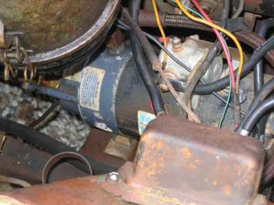
We mounted the pump along the passenger side frame rail, underneath the air cleaner. The air cleaner is visible on the left edge of the picture. Hoses, following the installation instructions, are routed along the inside of the frame, to protect them to the extend possible.
This is not an ideal setup. The multiple reservoir arrangement has made bleeding the system problematic. We continue to search for a better pump solution.
Arming
Major missing components were the implement lift arms and the linkage parts to the short lift arms. The good news is that the arms are simple metal bars. We have drawings from the instructions and pictures of other lifts that show the design. What we haven’t been able to obtain are actual dimensions. We attempted to use the drawings to calculate the dimensions and built wooden prototypes. Shown is a picture we received of a complete frame and a test fit with a mower of our wooden models.
Once we were confident that the length would work, we took the wooden model to our welding shop and had a set of arms made.
You will notice that our “linkage” is an “L” bracket attached to a “U” bracket by a bolt to allow some adjustment.
In operation, we actually flipped the “L” bracket (the leg extends from the top of the short arm), to increase the height of the implement lift. All the bolts are grade 8 and should handle any loads we might apply.
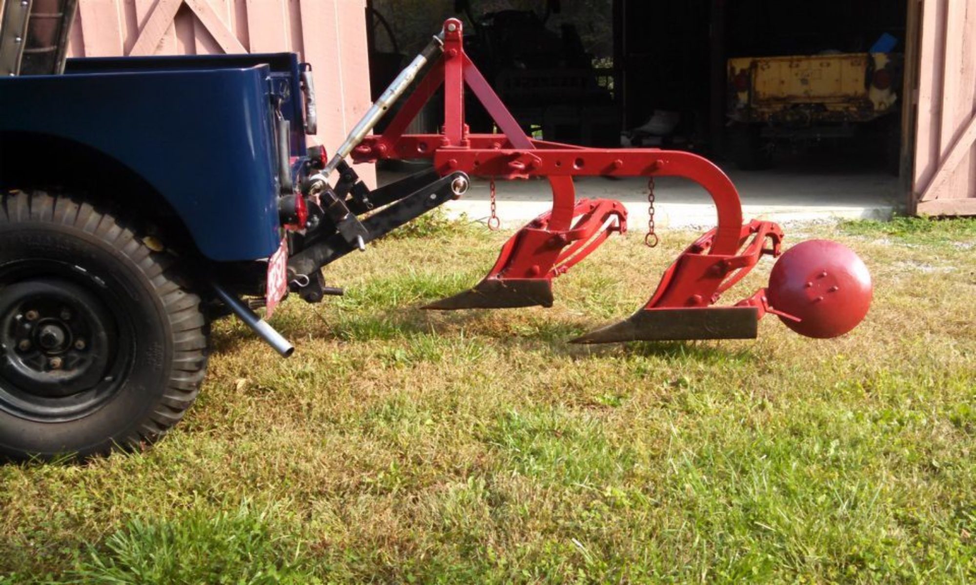
It works!
Shown are a couple of implements – a “carry-all” and a 2-14 plow (this is not the appropriate plow, but good for showing the concept).We expect to move the lift to the 3a we are restoring. As stated, we continue to search for a better pump solution. We also will continue to research the arms and linkages. But we do like many aspects of the Newgren design.
Originally posted 07/21/2003
Lift off
While we continue to search for an original Newgren lift pump, we made a strategic decision to find an alternative so we could make the lift operational. We have collected three different pump configurations. The first is the HY-LO pump normally used with a snow plow. It has its own control valve and reservoir. Since we wanted to use the control valve on the Newgren, this wasn’t going to be our first choice, although it is still a “possible” solution.
Pump number two, a Jack-LO is basically the HY-LO pump. This one arrived with a strange mounting bracket that won’t fit anywhere on the L-head. This one also remains a good “possible” solution with the addition of a fabricated mount.
The third option came in the form of a 12 volt electric pump with attached reservoir, but no control. While not true to the original design, later model Newgren lifts either came with or were retrofitted with electric pumps and controls. This option appeared to be the most straight-forward approach.
Plumb tickled
The first order of business was to plumb the lift to make sure it would work with the pump. Since the pump placement is going to be different for our three choices, we are starting with off-the-shelf parts from the local hardware and farm supply stores. This simple act resulted in no less than four hardware store runs and two farm store runs spread over two weekends. The hardware store is 20 minutes away and the farm store is 45 minutes away. The resulting “temporary” configuration is a jumble of “parts.”
We had mounted the lift (see part 10) temporarily and hadn’t been able to get it in the correct position. So Barry decided to remove the lift, lowering it enough to allow for easy access to the control valve and various hoses. It took Barry about an hour to slowly lower the lift.
Start’er up
The next task was to remove the old hardware from the pump and ensure it was in working order. The old hardware came off without a problem. Next was a quick electrical test. The motor is marked 12v and has a solenoid for on/off control. Barry attached jumper cables to the terminals and shorted the solenoid top control terminal to the positive cable. Nothing. He then shorted the positive terminal to the motor terminal and it sprung to life! Good news. Replace the solenoid and we should be set.
Luckily the chief mechanics were available to review the project. Barry’s dad suggested that the solenoid might be switched on the ground side. A quick test and it worked perfectly! Saved once again from replacing a perfectly good part.
5-4-3-2-1
Barry added a toggle switch across the solenoid and the ground terminal. When mounted in the jeep, we will place the switch on the dash and only use the pump when needed. After attaching the hoses, and filling both reservoirs as best he could, he throw the switch. LIFT OFF.
Well, actually, the cylinder did extend without anyone moving the control valve. It must have been stuck in the open position. Barry quickly turned off the pump and was able to move the valve to the “down” position and retract the cylinder by hand. He flipped the switch again and nothing happened. Perfect! He moved the control valve and the cylinder extended. Moved it to the down position and, applying a little weight, the cylinder arms went down. After the fourth or fifth cycle, the cylinder seemed to slow. More testing needed, but the weekend had ended.
Like a glove
Not having the Willys available for rides and work was enough of a motivator for Barry to get the lift back on. He was able to use a combination of jacks and wood blocks to get the lift in place. He had installed an elbow on a hose that he thought was preventing the lift from lining up correctly. It quickly became clear that the hose was fine and something else was preventing the rear of the lift from moving into the proper position. What the eye couldn’t see, the hand could feel. A muffler hanger bracket was still attached to the middle of the frame. The perfectly matching rust of the frame and bracket made it almost invisible.
A couple of busted bolts later, the lift slipped into place. There was still the matter of the bent bumper and a pry bar between the side rail and lift was required to get a bolt inserted. Tightening the bolt drew the passenger side into perfect alignment.
Weighing in
While on jacks, the lift had appeared to operate normally. With the lift attached to the frame, we were ready to do a real test. With Barry (weight not revealed, but plenty for testing purposes) standing on the short arms, Paula worked the rear controls. Barry had a quick trip up – a great feeling. However, if the control was returned to the neutral position, the lift dropped. Fluid appears to be leaking past the control valve. Bummer. It looks like a rebuild of the control valve will be needed. That means dropping the lift again. For now, on the advice of the chief mechanics, we will continue to operate the lift and see if the seals might swell enough to “heal” the leaking problem.
Like a glove – part II
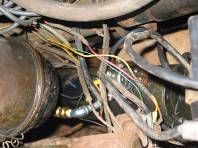
Ron Ingram’s CJ3B has the reservoir mounted in front of the battery (http://www.film.queensu.ca/CJ3B/Photos/Farm/IngramEngine.jpg). It appeared there is plenty of room for our pump there too. A quick measurement verifies that the pump should fit nicely. All that is required is to remove the starter switch and voltage regulator from the fender, along with removing the battery. The pump is heavy, about 30 pounds and will need to be securely fastened. The generator splash shield, while not supported on the engine side, makes a nice shelf. There also appeared to be a tie-in point near the motor mount; a pre-existing hole in the splash shield right at the motor mount aligns perfectly with the pump base. For now, that single bolt seems enough to prevent any movement. When we replace the body we will fabricate a more secure mount bracket.
The location made wiring a breeze. Short starter cables were run to the chassis ground bolt and to the hot side of the starter switch. The on/off switch was mounted in one of the radio knob holes for now. A quick test and everything is working great! We had considered adding a light to indicate the lift pump was running (to prevent running down the battery). The pump is actually quite loud, even audible when the engine is running, so that won’t be necessary.
Originally posted 09/08/2003
Up in Arms
It has been almost a year since we acquired the Newgren lift. We have continued to search for the missing implement arms and linkage, but haven’t been able to do better than a few pictures. Rather than wait, we decided to fabricate a set of arms, based on the documentation available.
Measure twice
The arms are actually very simple. Unlike most tractor arms, they don’t have knuckles (ball joints) on the ends. They are a simple metal bar with three holes. The linkage between the short lift arms and the implement arms was more complicated. In the end, we used a simplified linkage approach for now.
We first created wooden models, since we were going to have to have the metal bars made by a local welding shop. We based the length on the pictures we had and by attempting to scale the drawings included in the mounting instructions. Our test equipment was a bush hog, which would involve the PTO in addition to the lift. As can be seen from the picture, the arms were too short to allow the PTO hook up. This was a simple fix at this stage; we built a second set of wooden arms, adding 6” to the length.
Barry took one of the wooden arms as a pattern to his local welder. He also took copies of the pictures we had of the linkage. The building took a couple of weeks, and involved ordering the steel bar (3/4”) and sending the arms to a machine shape to have the large holes drilled. The machine shop broke a couple of bits and it delayed the process by a week. But the end product turned out well and the arms fit perfectly.
The linkage presented more of a challenge for the welding shop. In the end, they simply made an “L” shaped hanger and forged “U” brackets to attach to the implement arm. We are using ¾” grade 8 bolts to hold everything together.
Topping it off
While the arms where being made, Barry tackled the problem of the top link (the third point of the three point hitch) The pictures seem to show a two-part steel bar, with holes allowing for length adjustments. From a practical standpoint, this was a much inferior design to the more common screw-type top link. We may replicate the adjustable bar for show purposes, but for doing actual work, we will use a standard screw-type bar.
The top link on the Newgren is not as wide as those on modern tractors. Barry had to grind the “ears” off of the knuckle on one end of a store-bought link. It fits perfectly and allows for easy adjustments when mounting implements. That is a trait not shared by the implement arms.
The don’t make’em like that any more
When Barry finally picked up the arms, he couldn’t wait to try them out. The arms are very heavy; ¾” steel bars, 2 ½” wide and 30” long. The hangers are simple and still allow for height adjustments by raising or lowering the nuts. Everything fit perfectly and went together with a few bolts and pins.
Although not clear from the drawing or pictures, it appears that a bushing was used in the hole of the small lift arm. The holes where either cut to the rough dimension or have wear. In either case we felt a bushing was needed and are using a bronze type found at the local hardware store.
The hole thing
Once assembled, Barry drove the jeep out to meet the bush hog. He had several observations. First, while it is easy to see out the back, the lack of power steering makes aligning the lift and implement a challenge. Second, on a tractor, those knuckles on the end of the implement arm are forgiving; they allow you to slide the arm on even when not perfectly aligned. Not so with solid ¾” bars with holes just large enough to accept the implement pins. The Newgren method requires pulling, tugging and lots of swearing. This is going to take practice.
Much to his dismay, Barry discovered that one of the holes had been drilled to small. It was an 1/8” off. Back to the house and into town for a 7/8” drill bit to finish the job. But Barry did have enough evidence that the arms where the right length and that the thing might actually work.
Mower than we bargained for
A day and $10 (the cost of the bit) later, Barry tried mounting the bush hog again. After much backing, pulling forward, swearing and backing again, he got the arms on the bush hog and the top link attached. Now for the test. He pulled the control to raise the lift and … Squat. That is what the jeep did, but the bush hog wouldn’t come off the ground. Granted, this is the heaviest 3-point implement we own, but the Newgren should be able to lift it off the ground. More work is needed on the pump.
Going with the flow
Evan was able to come down for some more testing. Based on the advice of the chief mechanics, he added more fluid to the reservoir. He rode up and down on the arms a few times and declared it ready for another test.
This time the target was a plow. This plow a “2-14s” is bigger and heavier than the recommend “2-12s” but should be good for testing. Evan did the driving and Barry did the directing. It was clear that two people make the job of implement mounting much easier. With more tugging, the plow was mounted. Evan hit the lift switch and the plow came up – but just a little.
We disconnected the between-seats control lever to ensure we weren’t limiting the valve travel. It helped a little (we will need to adjust the forward rod when this is all working), but still not a full lift.
Back to the garage for more fluid and load testing. We both stood on the rear arms and worked the pump. One more time to the field and this time some success. However, it was clear that we have too much linkage space between the lift and implement arms. We could gain a couple of inches in height by flipping the “L” brackets over.
One more trip to the garage. The simple design of the linkage made the change easy. We replace the bolts with slightly (1”) longer versions and headed back out to the field. This time the target was an old carry-all. More tugging and pulling to get the carry-all mounted, but the lift worked better.
That doesn’t sound right
The lift valve is making lots of noise when under load. Although the instructions say “no adjustment need to the factory settings” it may be that 50 years of rust and dirt have taken their toll. More bleeding and cleaning seem to be in order and the underbody design makes it hard to get at the parts. We may just live with the slow lift for now and are seeking professional advice on next steps.
But at the end of the day, we have a real live working Farm Jeep!
Originally posted 09/15/2005
Pumped – Part II
Over the past few months, “Old Yeller” has been doing farm duty as pickup and wagon hauler. The 3 point lift simply hasn’t worked well enough to be a useful tool. The new tractor has a backhoe, and although relatively easy to remove and remount, it means a 3 point lift isn’t always available. So that was reason enough to revisit the lift.
Although our research (see part 11) showed a two reservoir system (one on the lift and one on the pump) should work, we have not been able to make the lift to work properly. So we decided to try using a pump without a second reservoir.
Our first attempt was to mount a Hy-Lo pump on the generator, rerouting the ram hose to the use the Hy-Lo control. We had the same issue – not enough lift. We also discovered a seal leak on the pump. Our conclusion was this wasn’t the solution.
Back to e-bay
Barry, in his daily wanderings through e-bay, found a used 12 volt pump, without a reservoir. This pump fit nicely in the same space occupied by the old pump/reservoir setup. In a rush to get a test done, connections were made to the ram and the Newgren reservoir. However, a quick test with the plow was another disappointment. The plow would not lift completely.
Time for the pros
Prior to and since acquiring his new tractor, Barry has been hanging around www.tractorsbynet.com. He took are lift questions to the parts and repair forum. Early suggestions included the possibilities of leaky “o” rings in the control valve. That seemed like a real possibility, since the valve doesn’t appear to have been touched in the past 50-some-odd years. Getting to the valve means dropping the lift.
By chance, another board member posted a question about how to learn about hydraulic systems. He was pointed to an Army Field Manual here.
Hosed
While reading the manual, Barry realized that he had failed to re-attach a small hose from the ram to the reservoir. For the ram to function properly, this hose needed to be in place. Since the Hy-Lo pump wasn’t set up for this line Barry had chosen to cap the ram. Now realizing that the return line served an important role, it also helped explain why the Hy-Lo pump hadn’t worked. The line had been in place with the old two reservoir system, so that eliminated it as a source of our problem there.
Up-lifting!
Somehow, in the process of changing out the pumps, the fitting need to reattach the return hose was lost. After a couple of trips to the hardware store, the proper fittings were found. Time for another field trip.
This time, the two-bottom plow lifted smoothly. Barry did notice a few leaks, so disconnected the plow and headed to the garage. After a few turns of the wrench, and taking the time to reconnect the between-the-seats control, back for another try. This time, the target was a 3 point blade. The blade is much lighter than the plow, but Barry had some real work to do, so off he went.
As the action shots show, the jeep worked like a real tractor, grading gravel in front of the new barn. The blade lifted smoothly and the between-the-seats control worked great.
Observations
Even with the pump running, the blade falls slowly. My guess is that the Tractor by Net pros are correct and the “o” rings are leaking. Since a rebuild of the control will require dropping the lift, we can live with the problem for now.
Originally posted 10/15/2008
Our plan all along had been to move the 3-point lift from the 2a and install it on the 3a. With the body at the paint shop, the time was right. While the Newgren lift was designed as an aftermarket installation it isn’t something you want to do often. We have gotten pretty good at installing and uninstalling the lift, using two floor jacks and cribbing. Jacking up the unit, which isn’t especially heavy but awkward to handle, lying on your back, and moving the lift around to allow inserting of the bolts took about 30 minutes. While we could do it faster, but safety is an issue and we value our hands and fingers. With the body off, we could reach through the frame and lift the Newgren in to place. You can actually see how to align the bolt holes and the process took no more than a couple of minutes. The installation will never be this easy again.
Pumps, pumps everywhere
We now have a collection of hydraulic pumps, including 12 volt models and two versions of Monarch belt driven “hi-lo” jeep pumps. The latter two were sent off for seal replacement. We continue our search for an original Newgren crankshaft driven pump. In the meantime, a NOS (new-old-stock) Monroe pump appeared on e-bay. We broke open our piggy banks and won the auction!
While we don’t know if the marriage (Newgren lift with a Monroe pump) is historically accurate, we are hoping they are the combination we have been seeking. We are having custom hydraulic lines built that will run from the front of the engine to lift.
Pulleying my leg
Barry has had experience with crank driven pumps before, on older tractors he has owned. When the new pump arrived, he went in search of the appropriate “coupler” (sometimes referred to as a “lovejoy coupling”) to mate the pump shaft to the crankshaft. His internet searching didn’t turn up a ready solution. He finally remembered that he had purchased a reproduction of a Monroe lift parts manual. A quick check showed that a special pulley – made with tabs – was required and the Willys part number was listed as well.
Off in search of another special part. However, a quick note to the G503 board yielded a very pleasant surprise. The part number shown in the manual was the standard equipment pulley from early in the 2a production period on and was readily available. Our engine was an older model and had a flat pulley face. Barry did a quick check of the 2a and sure enough, it had the correct pulley with the three prongs. A new pulley was ordered and installed.
On a historical note, Willys must have had plans for a number of crankshaft driven devices or assumed that the addition of a hydraulic pump would be a common option. This might warrant some more research.
Exhaustive research
A requirement of a Newgren installation is the relocation of the muffler, from under the bed to a driver’s side location. We had made this change on the 2a, following the instructions on the original Newgren installation documents. The cut we made placed the “hump” in the pipe in front of the rear axle. The 2a’s exhaust pipe is banged up and crushed where it passes over the axle. We choose to do our own measurements this time.
We also moved the rear hanger and we hope this arrangement will prove more durable.
Originally posted 01/09/2009
Evan has been patiently searching and waiting for a Newgren pump. The search, which began when we acquired the Newgren lift in 2003, came to an end when a complete pump appeared on e-bay and Evan was the successful bidder. Amazingly, all the parts were there, although one bracket arm was missing. That has been repaired by our local welding shop and looks like new.
We took the pump to a hydraulic repair shop and have just learned that it isn’t repairable. We (with the help of the shop) are searching for a substitute. If one isn’t available, we will see about a custom rebuild. We still have the option of installing the Monroe pump, so this shouldn’t slow us down on our goal to have the jeep ready for spring plowing.
Originally published 09/02/2012
It was clear from reactions at the shows we need to display the jeep with a plow on the back to really give people a clear idea of a jeep as a tractor. That means we need to get the lift working, again.
Over the years we have used different pumps to power the lift, but wanted to use an authentic pump and eventually found a Newgren pump and bracket. The pump was sent to a repair shop for reconditioning and was determined to be “worn out” and not repairable. This sent us on another search for a replacement pump.
One of the joys of working on old jeeps is that you get to meet interesting and extremely knowledgeable people. Our friend Lonnie knows his Newgren history and told us that the pump was the same as that used on the International Harvester model “C” tractor. After some time search for a pump, we found one on e-bay.

The pump has been sitting in a box for a while and we did mount it, but did not connect it to the crankshaft before the first show. So with no other shows planned, Barry decided to hook the pump up and give it a try. The pump is connected to the crankshaft by a solid rubber disc, which allows for some movement and alignment.
The first test was a failure. Barry suspected that the pump might be running backwards (it seemed to be pressurizing the tank). He reversed the pump manifold, but the ram did not move. At this point, Barry consulted with his friends over at the Tractor by Net (TBN) hydraulic forum about possible solutions.
At the suggestion of the TBN folks, we disconnected the hoses and placed them in a 5 gallon bucket half full of hydraulic fluid. The bubbles coming from the pressure side showed that the pump was working (and rotating correctly), but not primed. By pouring some fluid into the “suction hose” we were able to prime the pump and could see it working!
Uplifting
The Newgren lift hydraulic system is pretty basic. The pump supplies pressure to a control valve located on the top of the reservoir. When the control valve is in the “hold” (neutral) position, fluid enters the control valve and “dumps” directly into the reservoir. When the lever is moved to raise the implement, the pump pressure is directed by the valve to the top of the ram, pushing the ram rod out and raising the implement arms up. When the control valve is in the “lower” position, fluid in the ram is returned to the reservoir and the ram rod is pushed in by the weight of the implement.
Since we know the pump is working, we could reconnect the hoses (pressure side to the control valve and return side to the bottom of the reservoir). After adding fluid to the reservoir and working the control valve a few times, the arms moved up. Success! Sort of.
Any pressure on the arms would stop the upward movement. No way this is going to lift a 200 pound plow. We may still have a problem if the pump isn’t providing high enough pressure. Or the control valve, although we have taken it apart and cleaned it, may not be working correctly. And we have leaks in the system. Unfortunately, those leaks appear to be coming from the top of the reservoir, which means lowering (un-installing) the entire lift.
We have had the lift in and out of two jeeps on several occasions. While not a terribly difficult task, it is a hard balancing act, not unlike removing a transmission. So before we attack the leak, we are going to try and build something along the lines of a transmission jack to help us get the job done.
Originally posted 08/14/2014
After installing the new motor, we were ready to get the hydraulic pump attached and ready to work. Before remounting the pump, Barry wanted to replace the shaft seal, to cure the slow leak. As noted elsewhere, Newgren used the same pump found on an International Harvester Model C tractor. A search found that the seal was available and an order placed. When the seal arrived, it was a pretty simple process to take the pump apart and remove the old seal. The new seal was tapped in place and we were ready to mount the pump.
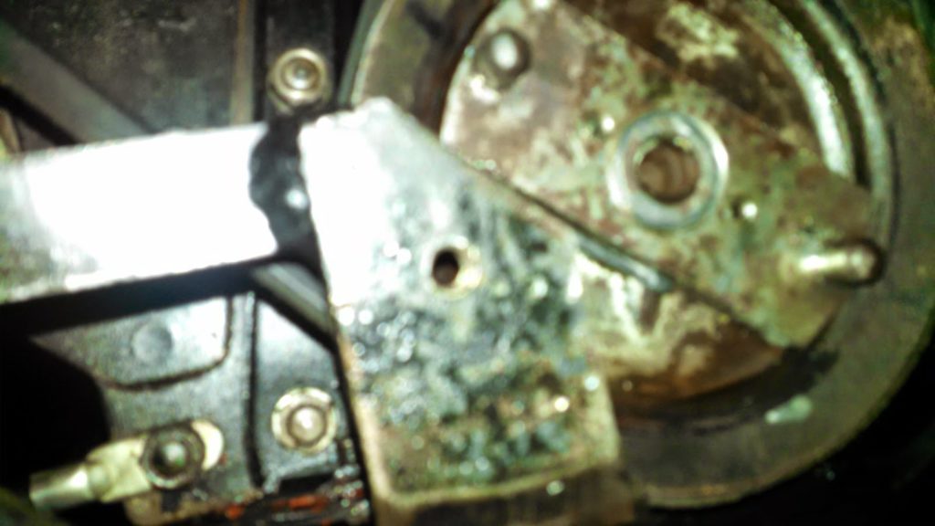
| Above is pictured a portion of the pump bracket and the crankshaft pulley with the “special nut” installed. Set screws (small dots) are visible on either side of the threaded crankshaft |
The pump connects to the crankshaft with a “special nut” (a steel bar with a short stud at each end), a rubber disk and a matching steel bar with studs that fits on the pump shaft. We have installed and removed the pump probably a dozen times over the years, so don’t need the installation instructions. Or so we thought.We quickly mounted the pump and started the engine. The lift worked perfectly for a few minutes. And then it stopped working. A quick inspection showed that the special nut had come loose from the pulley and was allowed the coupling to slip. The pump wasn’t turning fast enough to work. No problem, we just need to tighten the “special nut” on the crankshaft. Making sure it was tight, we tried again, with the same results.Time for a bigger hammer, or in this case a bar between the studs to REALLY tighten the nut. This did keep the nut from coming loose, but created a huge oil leak out the end of the crankshaft! Rather than report the hours spent trying to stop the leak, we will simply report the fix. We needed a new “slinger” behind the timing chain cover and, mostly importantly, we used Permatex Ultra Black sealer between the shaft and pulley. Time to attack the problem of the nut coming loose – over tightening was not the answer.It was clear that the problem had surfaced with the pump seal replacement. More force was required to turn the pump when it was not leaking (a good thing). The original instructions called for two small set screws on the “special nut” to be removed with the nut in place against the pulley. Two small holes were to be drilled into the face of the pulley (using the set screw holes as a guide). We had not figured out how to do this without removing the front of the jeep, so had just tightened the set screws against the pulley face.Figuring that the average farmer or Willys dealer would have not wanted to remove the radiator and grill, there must have been a method for drilling the holes. We have a right-angle power drill and it worked perfectly for the task. Regardless of the method used, the properly installed special nut hasn’t come loose. Another lesson learned for us. Follow the instructions!