An interview with Luke Schimmel of White Horse Manufacturing
Introduction: One of the most frequently asked questions at Farm Jeep is, “Where can I find a hydraulic lift and lift replacement parts?” We posted a Reproduction Lift Parts page with the names and contact details of the individuals we know who are producing parts. We met one of those individuals, Luke Schimmel, at the Spring Willys Reunion in 2022. Since that time, we have been working with Luke to expand the number of parts, especially Monroe Hydraulic Lift parts, that are available. We have asked Luke to educate us on the whole parts reproduction process as it exists today.
FJ: Luke, before discussing reproducing parts, we want to understand what you and your company do daily. Let’s start with your “Jeep story” and some background on how you arrived as head of your own company.
LS: Thanks for the opportunity to share my story. My Jeep journey actually began before I was born, with my Grandpa who fought in Korea and rode in a Jeep (M38) during his time overseas. When he returned from the war, he set his heart on owning a Willys Jeep. He was successful in his pursuit years later when a local golf course was selling their old plow vehicle; worn out, tired, and unloved, a CJ2A followed him home. For years he would have work done to the jeep to get it running and road worthy, which led to my Dad (Karl) learning to work on the jeep with a neighbor. Years of the Jeep running or not running led to me holding the flashlight for Dad all the way to sanding down the body and helping to paint the jeep. As I turned 18 I bought my first vehicle a project 1951 Willys Truck. I stripped that all the way down to the frame and built it (learning along the way) from the ground up.
During this process I was attending college at UW-Platteville (I was very popular in the dorms cleaning carburetors etc). While at Platteville I learned Mechanical Engineering and the skills of a Foundrymen. Once I graduated, I took a position at a family-run foundry where I moved from Project Engineer to VP of manufacturing, which I ran for 5 years before moving on to an Engineering position at a large Diesel engine manufacturer. At the same time as the move, I opened White Horse Manufacturing. At WHM I make Non Ferrous (aluminum, brass, and bronze) castings in-house, and weld, machine, and plasma cut parts. For the Iron castings, I design all the tooling, and make the molds, but have a local foundry pour the metal, then I bring the parts back and finish them in-house.
FJ: Thanks for that background. Your Jeep story is a fun one. Your entrance into the parts manufacturing industry is also very impressive.
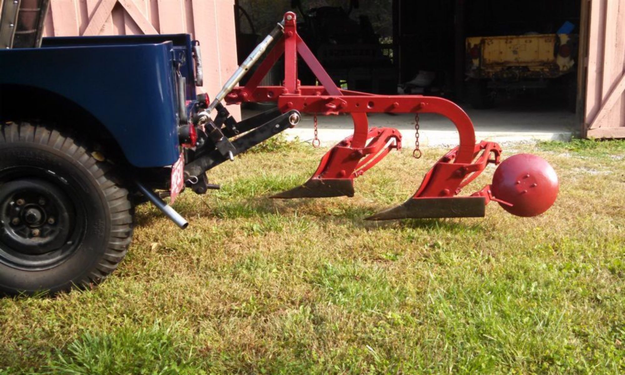
As you know, making reproduction parts for the Farm Jeep equipment isn’t a huge market. But for those of us who are trying to get these machines back in the fields, it is very important to have parts that can withstand the kinds of abuse handed out by farmers.
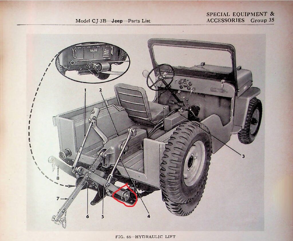
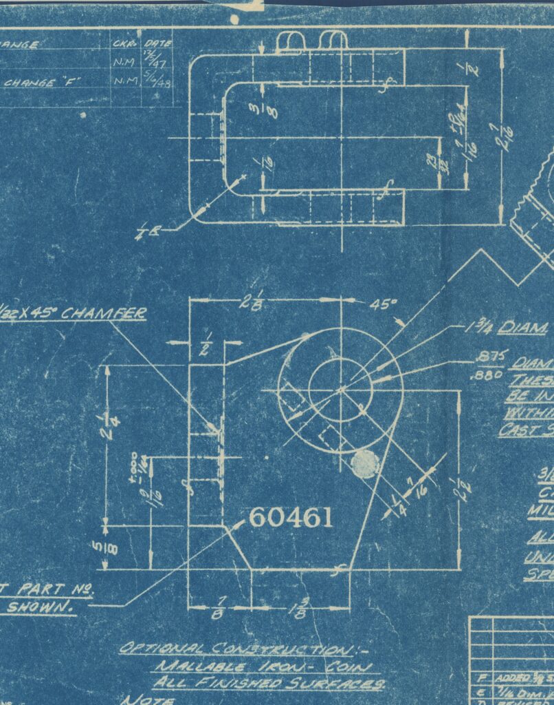
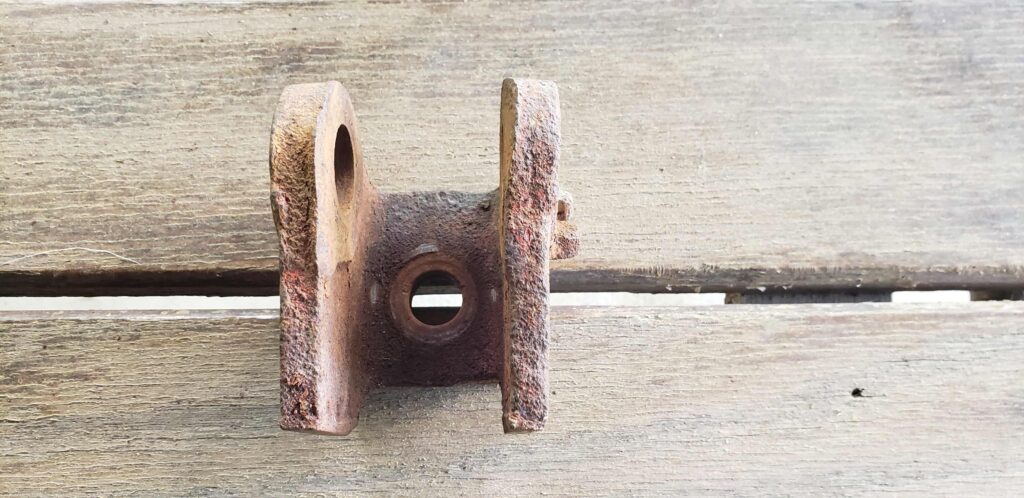
For a variety of reasons, smaller parts are missing from the lifts we find. Mounting brackets always seem to be missing. A good example is the “lower clevis,” which is part of the Monroe lift that is used to attach the lower link (implement) arms to the Jeep. We have been lucky enough to obtain the blueprint of this part (thanks to Keith Buckley) and have a rusty example.
So, a two-part question. First, how would that part have been produced back then, and would it be done differently if made today?
LS: Based on the blueprint of that part it would have been made with the sand cast process. The engineer would have drawn the part on the print then taken that to a pattern shop. At the pattern shop a skilled pattern maker would have sculpted the castable pattern out of wood, shaping the entire thing by hand with woodworking tools. The clevis being a more complicated part as it requires a sand core. Today I will use the 2D drawing to create a 3D model, that model will then have draft and core prints added to it. Once the model is complete I will either 3D print a pattern insert which will be mounted into a wood board, or CNC machine a pattern which will be mounted into the wood board. The difference between today and the original manufacturing of this part is how the pattern is constructed, the modeling and pouring process will be very similar to the original.
FJ: OK, so if we have a blueprint, you can produce a replica using the casting/machining method. A weldment process makes a piece that was dimensionally and functionally accurate but would not have some of the casting details (like the part number), correct? What are the advantages of each method, including cost (especially for a small number of pieces)?
LS: Excellent question, a casting has a few differences over a weldment. The original print calls for malleable iron or cast steel, the malleable iron will have completely different metallurgy that you will never be able to meet with a weldment. A casting is normally used for a few reasons, 1. When there is a complex weldment a casting is more cost effective. 2. When the geometry requires it. Castings have been used for over 5000 years; the process has evolved over that time but kept the core knowledge. For high production volumes the casting process yields a better-looking result, stronger part, cheaper part, and a more repeatable result. A casting puts the metal where you need it, and is not limited by geometry constraints.
A weldment is a fantastic thing when the geometry is simple, the metal required is commercially available, and when the part number is low. Weld tooling is very inexpensive, where as cast tooling is up front a higher cost. However, it quickly reduces that cost as the parts run more and more. Finally, a weldment may fail at the weld if a weld defect occurs, a good casting has the same properties throughout the entire material.
Both methods have a place, I personally use them both regularly, the part dictates which is superior. I would not cast a flat plate when I could just cut and bend one, I would cast a cylinder head instead of trying to cut and weld all of the passages together, the part needs to lend itself to the process.
FJ: We don’t have blueprints for the Newgren lift, but we do have original pieces. How can those be reproduced?
LS: When prints are not available, I can still make a part. I take the original part and if its small enough have its 3D scanned to make a model (this is very expensive so it is a last resort) or more commonly I will use measuring tools such as calipers, and micrometers to measure each feature of the part and create a 2D print, from there I will draw the part in 3D modeling software (CAD). Once I have a finished part drawn, I like to get either 2d or 3D prints made to the size of the part to validate the model against the original. When that is complete, I need to make the part castable, fill in any machined holes, add machine stock to machined features, and add cores to any features that require it. Finally, I add draft to the whole part and split it so I can make a pattern. Once I have the pattern, I can make a casting.
FJ: In some cases, such as the lift control valve, the original design could be improved by adding seals or “O” rings to prevent leak-down. Is that possible?
LS: Without a doubt, when I finish making a model for the part I can add any stock or features that the customer wants, to allow for the final part to meet their needs.
FJ: Luke, this is great information. Can you tell us more about pattern making and the casting process?
LS: Sure.
In order to make a casting first the foundry needs a pattern. The pattern is a replica of the finished part; however, it is larger than the part by the shrinkage amount. The shrinkage is the amount the part will physically shrink when cooling. The easiest way to explain this is to think of a claw foot bath tub, if one of the original legs broke and you took the leg to a foundry. If you told the foundry to pour you 1 leg using the old leg as a pattern the new leg would be roughly 1/8” per foot of length shorter than the original. So, if the original legs were 24” long then the new leg would be 23.75” long due to pattern shrink. So, with that the pattern maker must make the pattern larger than the original. The pattern maker must also add gating, core prints, and draft. Gating is the fluid path the metal will follow to fill the casting, proper gating yields a very nice and solid part, poor gating produces a weak and ascetically lacking part. Cores are sand cores or sacrificial sand put in the part to make voids or undercuts. For this we are only going to consider sand casting and no other form. To think of a core the easiest way is to picture a hollow tube or pipe, in order to cast the hole in the center a core would have to be made and placed in the mold. If the core was not placed then the casting would yield a solid cylinder of metal instead of a hollow tube. Finally draft, all sand cast patterns must have draft everywhere, draft is taper, allowing the release of the pattern from the sand. This is most easily pictured with an ice cube tray, the ice cube trays walls are all tapered toward the center, so the ice cubes can be easily removed. If a pattern is made without draft the sand mold will tear and a successful part will never be made. Now we can move onto sand casting.
Let’s talk about castings, specifically Sand Castings. What is a Sand Casting/ what is the sand-casting process? To answer those questions, we can travel through the process. A pattern is placed into a flask. The flask is a wooden frame or form placed around the pattern. Sand mixed with binder (clay and water) is placed into the flask and compacted. This causes the sand to become hard and hold its form, the flask is then stripped off the pattern, and the pattern removed. The 2 halves of the flask are then put back together to close the mold. The metal is poured into the mold and once solidified the mold is broken away from the solidified part. The sand is then reused for a future mold and the part cleaned.
FS: Wow! Great explanations! In the coming weeks (or maybe months) we hope to be able to add a virtual tour of your shop. As you begin to produce reproduction parts, we will come back for more details. Thanks again for taking the time to educate us.
LS: Your welcome. I look forward to some future visits.
Interview – Part 2
Luke Schimmel Interview – Part 2
FJ: Luke, thanks for helping us understand the parts reproduction process. We hear two types of requests for parts. There are those that are looking for parts to complete a lift that won’t see much use. Basically, they just want to display the equipment. The majority of requests are for parts that match the original equipment and can be used as intended.
Can you explain the different materials that you use in making parts, such as the Monroe lift clevis?
LS: This is an excellent topic. The original print calls for Cast steel or Mallable Iron.
As neither are defined on the print as to a specific grade, we have to assume the most common grades.
The steel of this time period would have had various grades. Modern cast steel generally calls for ASTM A216, Grade WCA, WCB, WCC.
The malleable iron is AST MA602 (for automobile grade)
WCA is the most common cast steel, very similar to ASTM A36 steel (the generic steel that anyone can buy at home depot, speedy metals, etc).
Malleable iron with 280M10 or 310M8.
Now the main alloys I make in-house are
Aluminum A356-T6
319
535
Brass C87500
and the outsourced ductile iron
65-45-12 and 80-55-06
So, let’s compare these items and what they would be the best at doing
A356-T6 is the most common cast aluminum. It is an aerospace grade that is very commonly used on commercial and military aircraft.
It is as strong as gray cast iron (the same iron used for a Willys engine block and transmission case and many more parts on the jeep). Where this aluminum does not do as well as iron is for wear resistance. However, it does elongate (stretch) before breaking. For anyone who has ever broken iron you know it doesn’t bend it just snaps/ cracks/ breaks. This aluminum does bend and is formable.
We will skip the other 2 aluminum grades for right now.
The Brass C87500 is a very strong silicon brass. This is a wear-resistant brass, a very good substitute I recommend for most iron castings, this material is stronger than low grades of steel and as strong as common steel grades. This material is better than the standard gray cast iron in almost every way. The drawback is cost.
Finally ductile iron
This is the modern superior version of malleable iron. Each grade of ductile iron is 1.5x better than every grade of malleable iron. For the true restoration of a Jeep, ductile iron or cast steel would be the most original.
For the cost-effective look and feel of the original, the cast aluminum would be the best choice. A steel bushing could even be added to the part in order to allow for higher loads. (it is important to note that the aluminum is 25% weaker than the original steel and iron). But at 1/3rd the weight its strength-to-weight ratio is higher than the iron. Please note this part will fully function and look great on any restoration, but anyone wishing to pull a plow through the dirt will want something stronger. For low-load implements such as brush hogs, earth augers, etc. these parts will allow a lifetime of use for any Jeeper.
For a compromise, a medium-cost part that will work and allow a functional restoration, the brass part is a perfect addition to anyone’s jeep. This part will wear and work just like the original iron. It will not rust, and will hold up to much more abuse, like a 3 bottom plow, box blade, or ripper teeth.
FJ: Very informative. We also asked you to take us through the design process. Where do we start?
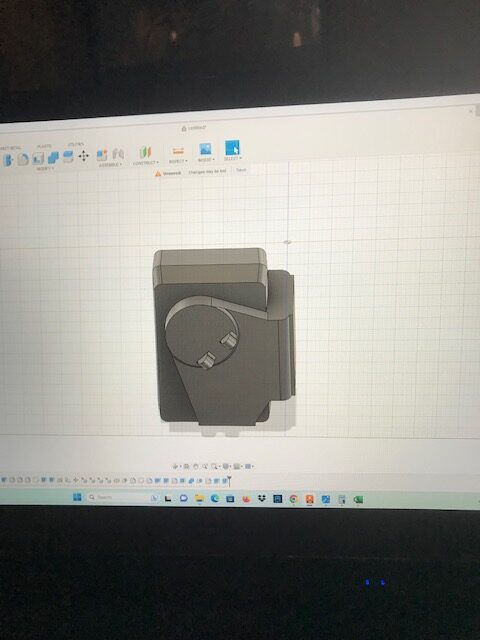
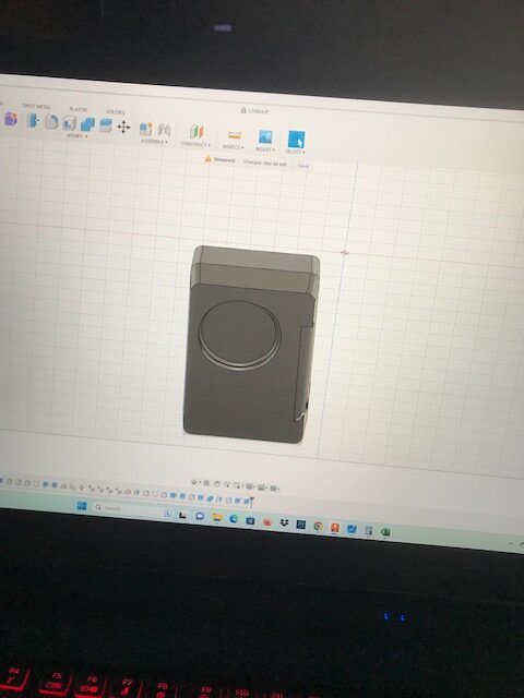
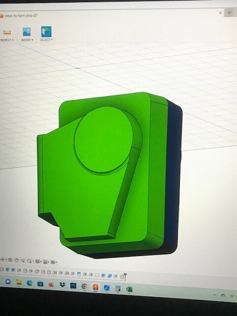
LS: This is the CAD process to start bringing this part back to life, first the part begins with a 2D sketch.
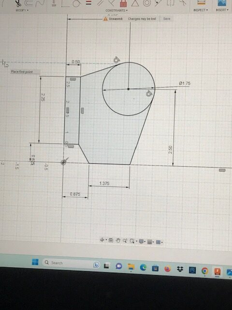
That sketch is then extruded to a 3D form ( 2nd photo) which then has a slot cut in it.
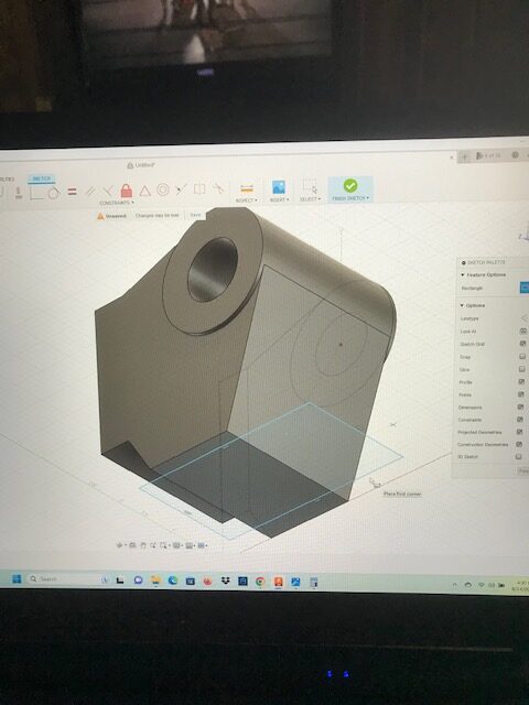
From there, I add the finished features to match the print for a finished machined part.
After that, I begin to add stock to the part (red areas). This is machine stock to ensure the part cleans up once cast.
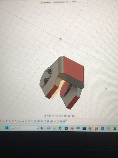
After that I will add a “core” . The core will be a separate piece of sand placed into the mold to make the slot in the part.
After that I add draft to the parts, shown in the photo in green and blue. The green is everything drafted to pull in a single direction. An important note here is that the middle cored area appears backwards, this is because cores are opposites.
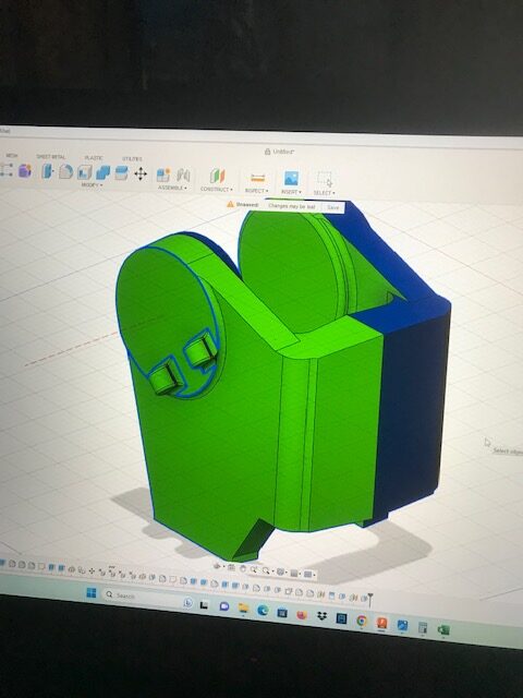
(Casting tooling really requires back-and-forth flips for proper draft).
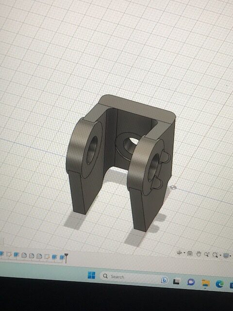
Once the part is verified that the draft is correct, then the core is placed inside the part and that is checked for proper draft. We now have a pattern. It is important to note the core sticks out beyond the actual part, this is known as a “core print”. The reason is that the print area is used to locate and balance the core, if the print is not large enough the core will tip and float when the molten metal enters around it, causing scrap parts.
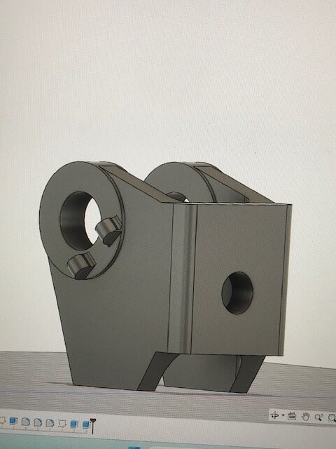
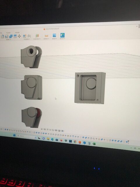
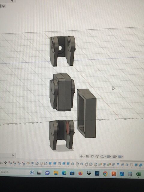
The last three photos are all the models in one. The finished part is on top, the pattern in the middle, the cast model on the bottom, and the core on the right side.
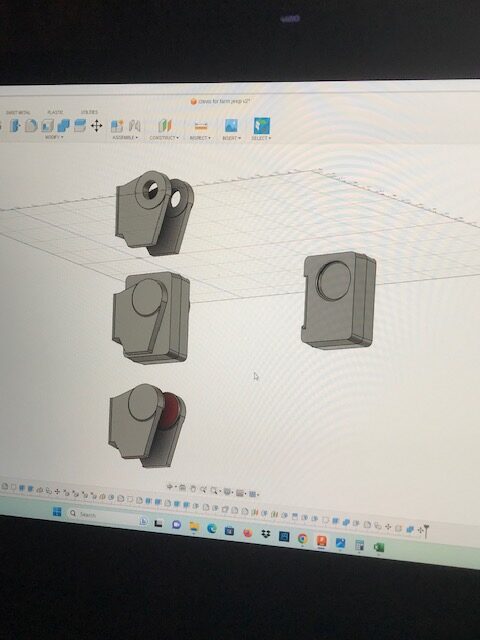
The final two have the core box instead of the core (the core box is the tool used to make the core). In this case, it is two halves that will have sand mixed with glue blown into them. The sand will then harden as the glue cures and the core is removed.
FJ: Thanks Luke! We look forward to hearing about the next steps.