In October 2021, Barry posted to the CJ2apage forum asking for help in finding more information about the Jeep Tractor Prototype. Member rocnroll posted:
Not to hijack this thread but those looking at this topic may be able to give a simple answer to something I was wondering the other day….
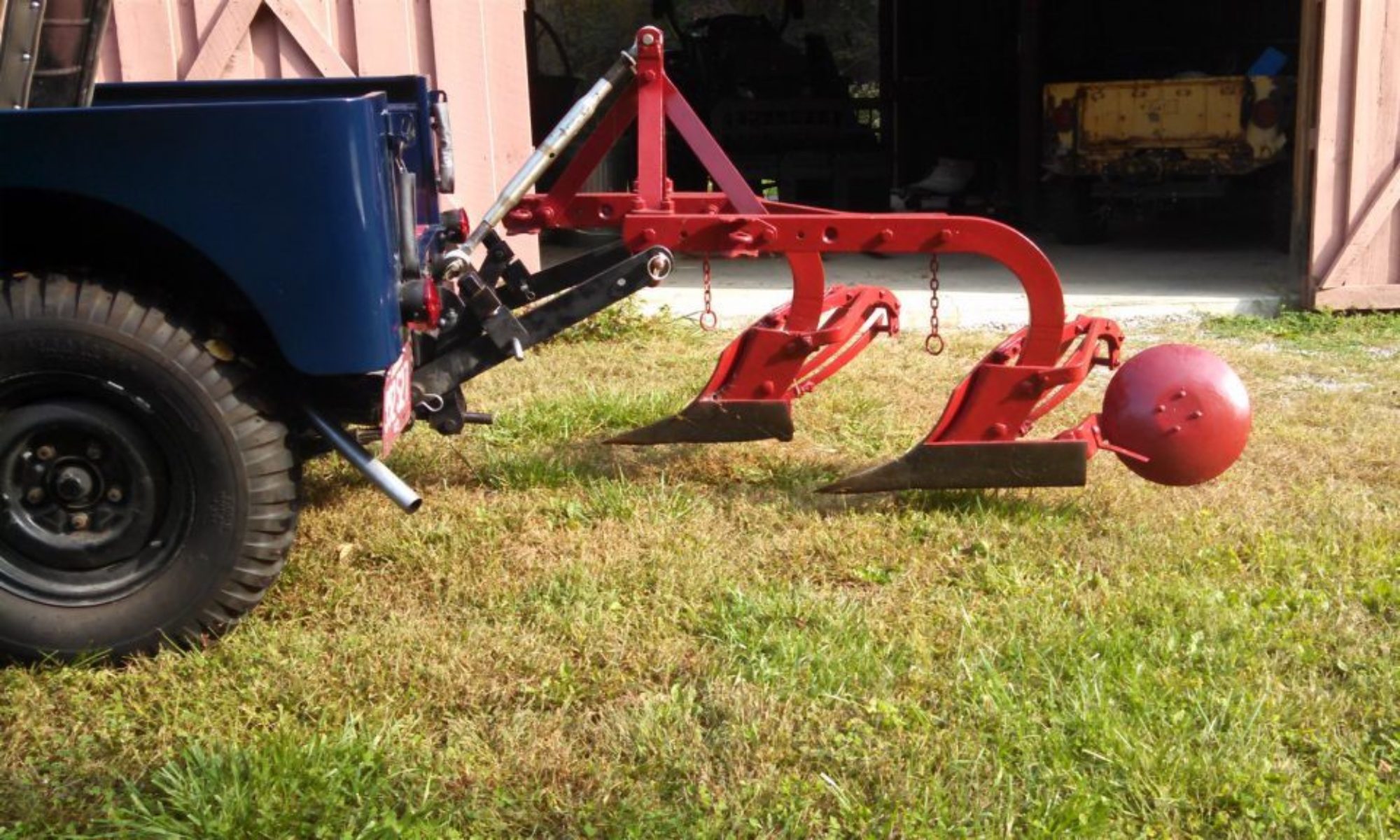
The triangular hitch ball mount on the draw bar has hole in the center….did this have a specific purpose or implement usage?
Barry suggested while he didn’t know the answer, it would be a good question to ask the antique tractor folks. The answer, however, came from our friend Clint Dixon:
I may be able to shed a little light upon the subject of the additional hole in the triangular hitch ball mount. My source is the publication titled: Tractors And Their Power Units, Second Edition, John Wiley & Sons, Inc. New York – London, copyright 1952.
To quote from Appendix E, page 478, ASAE Standard: 540-rpm Power Take-Off For Farm Tractors, “This standard establishes the specifications that are essential in order that any 540-rpm power take-off driven machine may be operated with any make of tractor having a a 540-rpm power take-off drive.
1. The diameter of the hitch hole (Fig. E1) at the end of the tractor drawbar shall not be less than 13/64 in., and, in addition, an 11/16-in. hole shall be provided in the drawbar 4 in. ahead of the hitch hole.
2. The material in the tractor drawbar shall clear an implement clevis (3 in. wide and having a 3-in. throat clearance) through a 90 degree swing right or left of the tractor drawbar center line.
3…”
…and the dialog carries on with more details of distances from the end of the splined PTO shaft, how far off center components can be to each other, etc.
I feel the pertinent information found in this particular ASAE standard, as it applies to the Jeep, indicates that WIllys-Overland was serious about meeting the existing standards in order to allow the vehicle to truly serve as a tractor. The paragraph above, labeled #2, shows that even though the vehicle already had a “drawbar”, the engineers were augmenting that existing design with the bolt-on triangular shaped addition. I believe it was not designed so much with the intent of it being a mounting point for a hitch ball, as much as it was to accommodate a clevis with the required swing that one with the mentioned throat clearance needed in order to function properly. And, of course to put the hitch point the correct distance from the end of the PTO shaft and the correct distance from the ground.
The paragraph above, labeled #1, clearly specifies the size of the hitch hole as well as size and location of the additional hole found in the triangular “drawbar”.
None of the above standards really explain a specific need for the additional hole, but they do indicate that this feature was a standard to abide by if one were to build a tractor. I have examined a LOT of antique tractors. Some adhered to this ASAE standard. Some did not. Kudos to Willys for giving it the old college try. I do not have personal knowledge of exactly what the intended purpose of that extra hole was. Maybe armed with this information, the truth can be found.
Clint